The Physics of the Coin Cradle
26 September 2026 · about 9 minutes
The Coin Cradle is a pendulum with a strong magnet at the bottom of its swing. A metal coin under the magnet brakes it, and a ratchet dial adds up how far it travels before it stops. This note explains the reading from first principles: the magnet, the currents induced in the coin, the energy lost on each pass, and how the dial counts. Every input is a measured dimension or a handbook value. Nothing continuous is fitted.
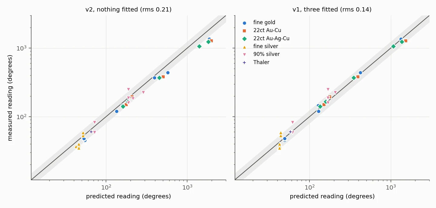
- With nothing fitted, the model predicts the 38 readings on Cradle #0001 to 21% rms.
- With one fitted number, the pivot friction, the error falls to 14.7%.
- What it says about fakes is modelled, not measured: no counterfeit has yet been tested on the device.
The instrument
The magnet is an N52 neodymium ring, 23.4 mm across and 20 mm tall, with a 6.1 mm bore, magnetised along its axis. It weighs 60.4 g. Its remanence, the strength of the magnetised material, is 1.42–1.47 T for the N52 grade.
The pivot is fixed 142 mm above the deck. The magnet height is set with spacers that work as 3 mm gauge blocks: they set the magnet face 3S mm above the deck for S spacers, and are removed before the test. The coin lies on the deck, so for a coin of thickness t the gap between the magnet face and the coin is
The pendulum is released from 50°. The coin rests on its rims, so the model places its metal as a slab of effective thickness t_{\text{eff}} = m / (\rho \pi R^2) centred at half the rim height.
What moves
The moving parts are the magnet, a 48.2 g rod, a 32.7 g cross axle and a 4.27 g side screw. Their moment of inertia about the pivot is 1.238, 1.180 and 1.124 × 10⁻³ kg·m² at one, two and three spacers. The magnet contributes 82% of it, the rod 18%, and the axle and screw 0.1% together. The pivot-to-magnet-centre distance is 142 − 3S − 10 mm: 129, 126 and 123 mm.
Changing the rod's inertia by ±15% moves every predicted reading by only ±1.4%, so the drawings of the rod matter little.
Eddy-current braking
As the magnet passes over the coin, the changing field drives loops of current in the metal. Those currents make their own field, which opposes the motion and turns the pendulum's energy into a little heat in the coin.
The field. An axially magnetised ring is equivalent to magnetic charge on its two flat faces. On the axis, at a depth h below the near face, the field has a closed form (outer radius Ro, inner radius Ri, height H):
At Br = 1.445 T this gives 0.255 T at 3 mm and 0.176 T at 10 mm. Off the axis the model integrates the field numerically; the two agree on the axis to 2 × 10⁻⁵. Because of the bore, the field falls again very close to the face (0.08 T at 1 mm).
The drag. At these speeds the braking force is proportional to the speed, F = c v, with a coefficient
Here σ is the coin's electrical conductivity, \hat B_z = B_z/B_r is the field shape, and ψ is a stream function for the currents in each thin layer of the coin. The braking is therefore exactly proportional to σ, and grows with the coin's thickness. The formula has no free scale: it reproduces the textbook thin-sheet result for a point magnet exactly.
Why a thin-disc model is valid. The magnet crosses the coin at 1.3–2.0 m/s. The characteristic speed of the sheet, w = 2/(\mu_0 \sigma t), is 10 m/s for 1 oz silver and 18 m/s for 1 oz fine gold, so the currents barely distort the field (a correction of at most 3% on the first pass). A pass is a half-cycle at about 40 Hz, where the skin depth is 10–12 mm, against coins 1–3.3 mm thick. The test reads the coin's whole thickness, not only its surface.
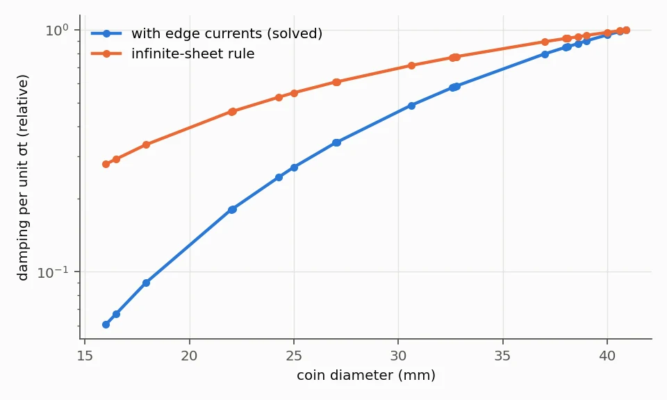
Edge currents. The currents cannot cross the coin's edge (the ψ = 0 condition). A uniform field drives no current; only the change in field across the coin does. So a small coin sitting under the flat centre of a large magnet is braked far less than a simple “infinite sheet” rule predicts. In the earlier fitted model, removing the edge currents doubled the error, from 13.8% to 28%.
The energy method
The pendulum obeys
where Rf is the distance from the pivot to the magnet face, x = Rf sinθ is the magnet's position along the coin, and τf is pivot friction. The gap grows as the magnet swings out, h = h_{\text{gap}} + R_f(1-\cos\theta), so the magnet lifts off the coin; this arc is set by the geometry, not fitted.
The release puts in a fixed amount of energy:
Each pass over the coin removes \int c\, v\, dx. The braking is small beside gravity, so the swing dies away over several passes, and the total travel is set by the ratio of the release energy to the energy lost per pass. That is why the reading falls roughly as one over the coin's conductivity. The model integrates equation (4) numerically from 50°, and checks its step size to 10−5.
The ratchet dial
The dial is marked “turn clockwise only” and records cumulative degrees, including full turns, so it is ratcheted. No document described how it is driven. The model tested three rules, each with a one-to-one drive and nothing fitted:
| Dial counts | rms error, 38 readings | Mean bias |
|---|---|---|
| All travel in the return direction | 0.74 | predicts 2.0× too high |
| Outward strokes on the far side only | 0.21 | +0.16 |
| Outward strokes on the release side only | 0.33 | −0.16 |
The data pick the second rule: the dial advances only while the pendulum swings outward on the side away from the release. The model inferred this from the readings; it has since been confirmed on the device.
Results
The model predicts 38 of the 44 readings in the Cradle #0001 workbook (the other six are clad coins with no listed conductivity).
- Nothing fitted: 21% rms (20.9%) in the log of the reading. The model reads 16% high on average, and 68% of readings fall within ±25%.
- The error is largest for the fractional coins, which take longest to stop. For the 1/10 oz coins the prediction is 37–55% high, which points to pivot friction the model leaves out.
- One fitted number: 14.7%. Adding a pivot-and-dial friction torque of τf = 1.5 × 10⁻⁴ N·m (19% of the specification's upper bound) gives 14.7%, and the same 14.7% when each reading is left out of the fit in turn.
- The hardware uncertainties are much smaller than this: the N52 range moves every reading by ±3.5% (braking goes as Br²), the rod inertia by ±1.4%.
Telling fakes apart (modelled)
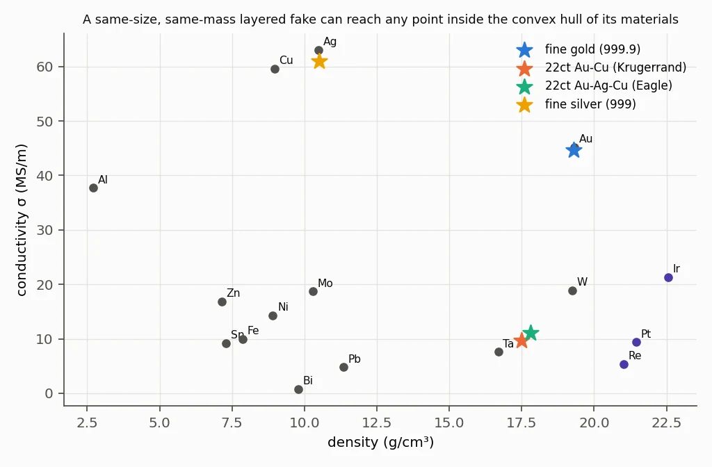
For a fake of the same size, the reading depends on the conductivity times thickness of each layer, weighted by depth. A counterfeiter who must match the coin's size and weight can reach any point inside the envelope of the materials they use. The table uses handbook conductivities and densities. All of it is modelled; no fake has been measured on the Cradle.
| Genuine coin | Fake (same size and weight) | Reading, fake ÷ genuine | Noise widths vs a reference coin |
|---|---|---|---|
| Fine gold | Gold-plated tungsten | 2.37 | 19 |
| Fine gold | Silver + iridium stack | 1.36 | 6.8 |
| 22 ct Krugerrand | Tungsten + copper | 0.38 | 22 |
| 22 ct Krugerrand | Tantalum 72% + tungsten 28% | 0.90 | 2.3 |
| 22 ct Krugerrand | Tungsten + bismuth + rhenium | 1.00 | 0 |
| 22 ct Eagle | Tantalum 60% + tungsten 40% | 0.92 | 1.9 |
- Fine gold is well protected. No cheap metal is both denser and more conductive than tungsten, so a plated-tungsten fake reads about 2.4 times a genuine coin.
- 22-carat coins are the weak point. Their conductivity (9.7–11.1 MS/m) lies among cheap dense metals. An engineered tantalum–tungsten stack reads within about 10%, and adding rhenium can match exactly. Testing both faces catches stacks that are not symmetric, and the ping test and a careful weight check remain part of the workflow.
- Compare against a reference coin. Against the formula the noise is 15–21%; against a genuine coin of the same type on the same unit it is estimated at 2–5%. That is the largest gain available, and it is why an eddy-current pass on this site needs a reference coin.
What the model does not yet cover
- Pivot friction is the main error left, and it is fitted, not measured. A single release with no coin, timed to rest, measures it directly and removes the last fitted number.
- Individual swings. The workbook holds averages only. Ten releases per coin, including a plated-tungsten fake, would give the first measured fake and the first real noise figure.
- Coin rims. Some rim thicknesses are catalogue values; callipers would settle them.
- Other devices. The model is built for Coin Cradle #0001. The printed kits have different magnets and pivots and are untested.
The earlier empirical formula (historical)
Before this model, the Cradle's readings were described by a power law fitted to 38 readings on Cradle #0001:
The constants K = 488 and C = 2.90 belong to that one unit. The σ0.998 is what the physics requires (braking ∝ σ). The volume exponent 1.431 is not a physical law: it stands in for three separate effects, the coin's thickness, the thicker coin sitting closer to the magnet, and the coin's diameter through the edge currents.
| Model | Numbers fitted | Error (rms) |
|---|---|---|
| Power law above | 4 | 13.9% (leave-one-out, 31 readings) |
| v1 physics, invented magnet | 3 | 13.8% (leave-one-out, 31 readings) |
| v2 physics, measured hardware | 0 | 21% (38 readings) |
| v2 physics + pivot friction | 1 | 14.7% (leave-one-out, 38 readings) |
The fitted models are slightly more accurate, but their numbers absorb errors the physics now names. The v1 fit put the spacer at 3.36 mm where it is 3.0 mm, and its gap could not be identified. The v2 model is less flexible and more honest: what it gets wrong points to something specific to measure.
Technical reports
The full derivations, data tables and assumption ledgers. The v2 report notes that the dial rule was later confirmed on the device.